Basic GPIO BL702
The BL702 chip has 15 GPIOs. Each pin can be selected as one of the following modes:
ANALOG_MODE
Used as a function pin, input and output analog.
INPUT_PULL_UP
Input with an internal pull-up resistor - use with devices that actively drive the signal low - e.g. button connected to ground.
INPUT_PULL_DOWN
Input with an internal pull-down resistor - use with devices that actively drive the signal high - e.g. button connected to a power rail.
INPUT_HIGH_IMPEDANCE
Input - must always be driven, either actively or by an external pullup resistor.
OUTPUT_PUSH_PULL
Output actively driven high and actively driven low - must not be connected to other active outputs - e.g. LED output.
OUTPUT_OPEN_DRAIN_NO_PULL
Output actively driven low but is high-impedance when set high - can be connected to other open-drain/open-collector outputs. Needs an external pull-up resistor.
OUTPUT_OPEN_DRAIN_PULL_UP
Output actively driven low and is pulled high with an internal resistor when set high - can be connected to other open-drain/open-collector outputs.
OUTPUT_OPEN_DRAIN_AF
Alternate Function Open Drain Mode.
OUTPUT_PUSH_PULL_AF
Alternate Function Push Pull Mode.
Using GPIO#
The relevant functions are defined in hosal_gpio.h. Include this header before using any GPIO functions. An example application is as follows:
#include <stdio.h>
#include <hosal_gpio.h>
#include <FreeRTOS.h>
#include <task.h>
static hosal_gpio_dev_t gp1;
void main (void)
{
// setup
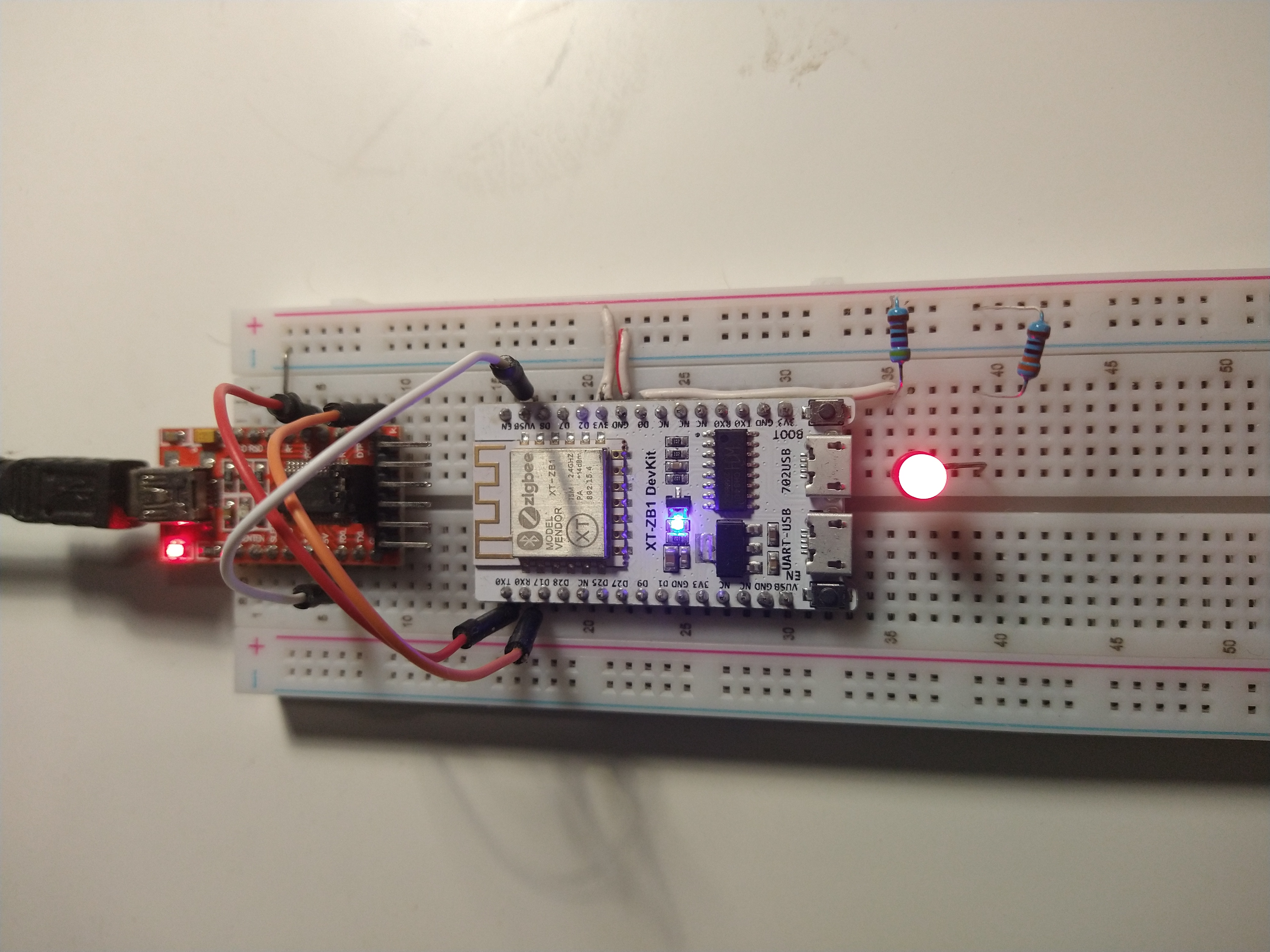
gp1.port = 0; // <== make sure led connected to pin D0!
gp1.config = OUTPUT_OPEN_DRAIN_NO_PULL;
hosal_gpio_init(&gp1);
hosal_gpio_output_set(&gp1, 1);
uint8_t value = 1;
while (1) {
hosal_gpio_output_set(&gp1, value );
value = !value;
vTaskDelay(500);
}
}
Before we could use the GPIO API, the GPIO struct must be defined and assigned as in line6. Here we're naming it as gp1 to reference later.
Then we must initialise and config a GPIO pin before we can use it. This tas is done in lines 11-13.
The possible value for the 'config' setting was introduced in the start of this article; see above. Finally call the function hosal_gpio_init. Now we can use the API to control them.
As basic functionality of GPIOs, we set the output levels using the following commands:
hosal_gpio_output_set(hosal_gpio_dev_t *gpio, uint8_t value)
Value 0 sets the pin in logical 0 / inactive state. Value 1 sets the pin in logical 1 / active state.
To read an input:
hosal_gpio_input_get(hosal_gpio_dev_t *gpio, uint8_t *value)
I've looked for a GPIO 'toggle' function to simplify this example, but unfortunately the API docs do not indicate any...
Interrupt Mode#
We look into interrupts using GPIO pins. Each GPIO can be set as an interrupt function. The main idea is to register a callback functionusing the Interrupt API, and define it's contents. As follows:
#include <stdio.h>
#include <hosal_gpio.h>
#include <FreeRTOS.h>
#include <task.h>

static hosal_gpio_dev_t gp1;
static hosal_gpio_dev_t key1;
uint8_t value = 1;

void key1_irq(void *arg)
{
   hosal_gpio_output_set(&gp1, value );
   value = !value;
}

void main (void)
{
   // setup
   key1.port = 8; // the d8 button; note that it's active LOW
   key1.config = INPUT_HIGH_IMPEDANCE; // button includes external pullup
   hosal_gpio_init(&key1);
   hosal_gpio_irq_set(&key1, HOSAL_IRQ_TRIG_NEG_PULSE, key1_irq, NULL); // 'key1_irq' indicates the desired procedure at interrupt.

   gp1.port = 5;
   gp1.config = OUTPUT_OPEN_DRAIN_PULL_UP;
   hosal_gpio_init(&gp1);
   hosal_gpio_output_set(&gp1, 1);

   while (1) {
   }
}
Line 10 defines the callback function named key1_irq. Here we are simply toggling the D8 LED.
Initialising the Interrupt requires a string of statements beginning on line 19. Notably we initialise it as an input Pin as we covered in the previous section. Then finally use the 'irq-set' function to configure it and indicate our callback function. Note that we had to define the device on line 7.
This is a very basic demonstration of push button with no debounce mechanism. The led may inadvertently toggle multiple times for a single push.
ALT Function Mode#
This is the secondary mode of each GPIO PIN where we tie it to the required peripheral. We'll look at setting up the PINs for alternate function as we deal with the relevant peripheral.