Understanding the Clock Subsytem
As mentioned, the vendor provides a repo of examples for their various chips. You can study them to use the various peripherals. So we won't repeat them here. But we'll discuss one crucial component - the clock.
One peculiarity of these Si-Labs chips (at-least the efr32Xg21 family) is they take a fixed 38.4MHz crystal for the external source. This simplifies a lot of the clock setup configs.
Here is a basic diagram with the most used components.
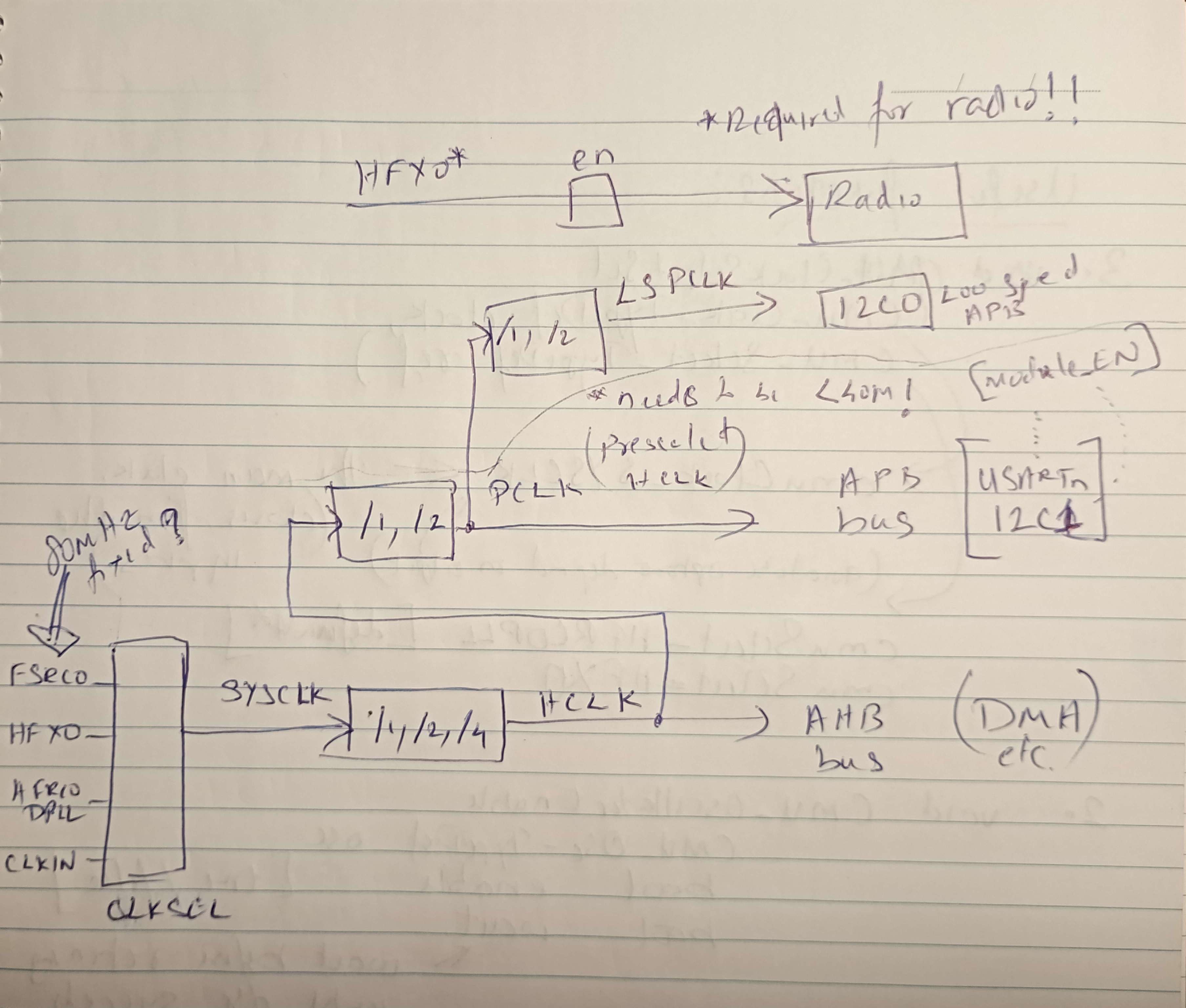
Note that the chip boots on FSRCO then switches to HFRCODPLL before executing user firmware.
Setting up for external crystal#
Our ZYZBP008 module comes with an external crystal attached (according to the datasheet, it is mandatory to source from the external clock to enable the radio unit). Here is a code excerpt from the example repo on how to configure for the external source:
#include "em_cmu.h"
#include "em_chip.h"

int main(void)
{
  CHIP_Init();

  // Start the HFXO with safe default parameters
  CMU_HFXOInit_TypeDef hfxoInit = CMU_HFXOINIT_DEFAULT;
  CMU_HFXOInit(&hfxoInit);
  CMU_OscillatorEnable(cmuOsc_HFXO, true, true);
  //                            enable^     ^wait until clock succeeds before returning

  // Switch the SYSCLK to the HFXO.
  CMU_ClockSelectSet(cmuClock_SYSCLK, cmuSelect_HFXO);

  while(1);

  return 0;
}
Lookup for these functions and their possible options in the clock component documentation. CMU_HFXOINIT_DEFAULT is defined in em_cmu.h and apparently suitable in most usual cases.
To verify that it works, we will test the UART peripheral (which is time sensitive).
#include "em_cmu.h"
#include "em_chip.h"
#include "em_gpio.h"
#include "em_usart.h"

#define BSP_BCC_TXPORT  gpioPortA // A05 - TX
#define BSP_BCC_TXPIN   5 //
#define BSP_BCC_RXPORT  gpioPortA // A06 - RX
#define BSP_BCC_RXPIN   6 //

int main (void)
{
  CHIP_Init();

  // Start the HFXO with safe default parameters
  CMU_HFXOInit_TypeDef hfxoInit = CMU_HFXOINIT_DEFAULT;
  CMU_HFXOInit(&hfxoInit);
  CMU_OscillatorEnable(cmuOsc_HFXO, true, true);

  // Switch the SYSCLK to the HFXO.
  CMU_ClockSelectSet(cmuClock_SYSCLK, cmuSelect_HFXO);

  CMU_ClockEnable(cmuClock_GPIO, true);
  GPIO_PinModeSet(gpioPortA, 0/*pin 4*/, gpioModePushPull /*push-pull output*/, 1/*output level*/);

  CMU_ClockEnable(cmuClock_USART0, true);

  USART_InitAsync_TypeDef initAsync = USART_INITASYNC_DEFAULT;
  initAsync.baudrate = 115200;

  GPIO->USARTROUTE[0].TXROUTE = (BSP_BCC_TXPORT << _GPIO_USART_TXROUTE_PORT_SHIFT)
            | (BSP_BCC_TXPIN << _GPIO_USART_TXROUTE_PIN_SHIFT);
  GPIO->USARTROUTE[0].RXROUTE = (BSP_BCC_RXPORT << _GPIO_USART_RXROUTE_PORT_SHIFT)
            | (BSP_BCC_RXPIN << _GPIO_USART_RXROUTE_PIN_SHIFT);

  GPIO->USARTROUTE[0].ROUTEEN = GPIO_USART_ROUTEEN_RXPEN | GPIO_USART_ROUTEEN_TXPEN;
  USART_InitAsync(USART0, &initAsync);

  GPIO_PinModeSet(BSP_BCC_TXPORT, BSP_BCC_TXPIN, gpioModePushPull, 1);
  GPIO_PinModeSet(BSP_BCC_RXPORT, BSP_BCC_RXPIN, gpioModeInput, 0);

  //USART_Tx (USART_TypeDef * usart, uint8_t data)

  char buf[] = "Hello";

  while(1) {
    GPIO_PinOutToggle(gpioPortA, 0/*pin 4*/);

    for (int i = 0; i < 6; i++) {
      USART_Tx (USART0, buf[i]);
      USART_Tx (USART0, '\n');
    }

    for (volatile uint32_t i = 0; i < 100000; i++) { } // busy delay
  }

  return 0;
}
The above code should print Hello via serial repeatedly with the roughly specified pauses.