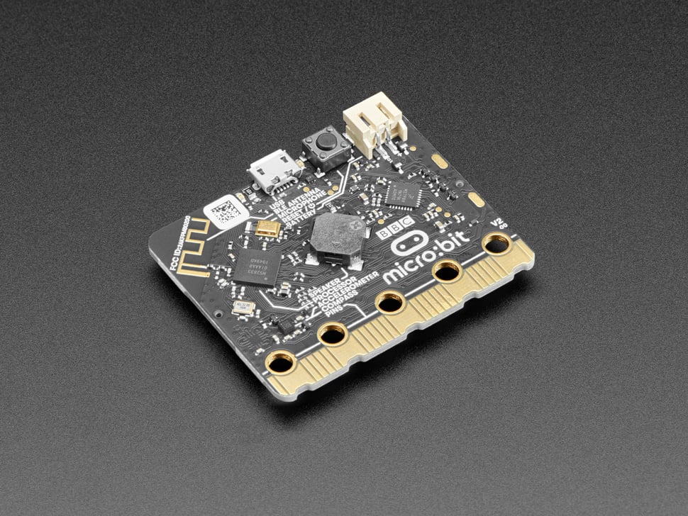
Micro:Bit IO breakout board
As we have seen prevously, we have switched our interest to the Nordic family of chips.
Providing a whole portfolio of low-power wireless microcontrollers, we are spoiled for choice when it comes to IoT centric projects. Given that 99% of embedded projects these days is somehow IoT based, this is the rationale behind going for these chips. Infact RF is in the name for Nordic, think nRF (the name of their mcu range).
In a wide range of Nordic chips our go-to is the nRF52833 controller. I find it has the right balance of cost vs performance. Detailed info of this chip here.
Now there are two viable hobbiest boards for this MCU1.
- nRF52840 Dongle [Which uses a similar chip only difference being double RAM/ROM]
- Micro:Bit v2

I choose the Micro:Bit. Here's why.
It packs in a lot of on-board sensors, which can be beneficial to quickly getting up and running; and at a reasonable price overhead. It retails for around $17.
It is also widely available.
Although its initial concept was to aid in kids' programming education; it has found its way into the arsenal of the serious firmware developer. Now isn't that a very familiar story?
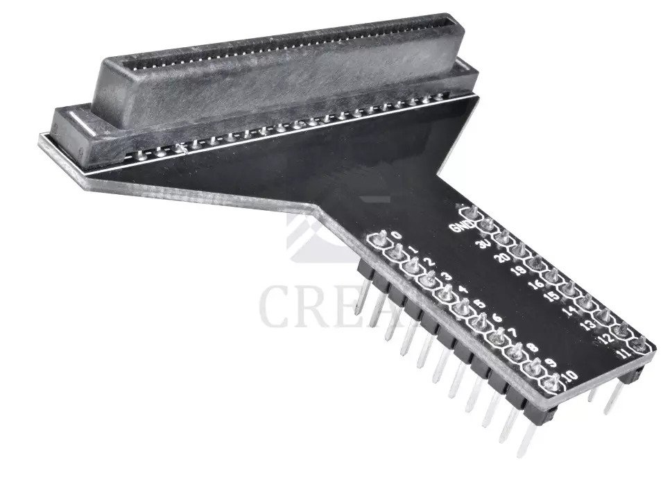
But there is one hurdle in using the Micro:Bit in breadboarding prototypes. There is a solution to this. Enter, the T-type breakout board.

It can be procured from Aliexpress here. Here's an excerpt of the board's device tree in Zephyr that conveniently shows the GPIO mapping of the nRF52833 to the marked pins in the breakout board.
edge_connector: connector {
		compatible = "microbit,edge-connector";
		#gpio-cells = <2>;
		gpio-map-mask = <0xffffffff 0xffffffc0>;
		gpio-map-pass-thru = <0 0x3f>;
		gpio-map = <0 0 &gpio0 2 0>,	/* P0 */
			   <1 0 &gpio0 3 0>,	/* P1 */
			   <2 0 &gpio0 4 0>,	/* P2 */
			   <3 0 &gpio0 31 0>,	/* P3 */
			   <4 0 &gpio0 28 0>,	/* P4 */
			   <5 0 &gpio0 14 0>,	/* P5 */
			   <6 0 &gpio1 5 0>,	/* P6 */
			   <7 0 &gpio0 11 0>,	/* P7 */
			   <8 0 &gpio0 10 0>,	/* P8 */
			   <9 0 &gpio0 9 0>,	/* P9 */
			   <10 0 &gpio0 30 0>,	/* P10 */
			   <11 0 &gpio0 23 0>,	/* P11 */
			   <12 0 &gpio0 12 0>,	/* P12 */
			   <13 0 &gpio0 17 0>,	/* P13 */
			   <14 0 &gpio0 1 0>,	/* P14 */
			   <15 0 &gpio0 13 0>,	/* P15 */
			   <16 0 &gpio1 2 0>,	/* P16 */
			   <19 0 &gpio0 26 0>,	/* P19 */
			   <20 0 &gpio1 0 0>;	/* P20 */
};
For an updated post of a newly available alternative see this post.